
0
Owner's of the Friedrich Air Conditioner Friedrich Room Air Conditioners gave it a score of 0 out of 5. Here's how the scores stacked up:
26
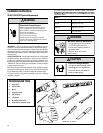
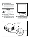
CAUTION
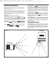
Remove Shipping Blocks
Prior to operating the unit remove
the foam shipping blocks.
Failure to do so may result in
damage to the unit which is not
covered by the manufacturer’s
warranty!
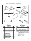
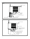
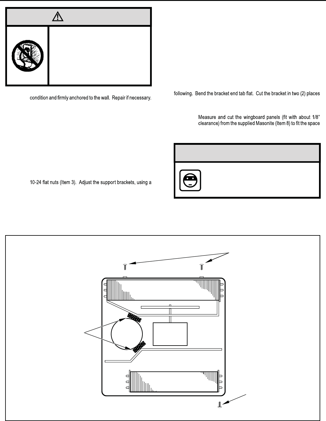
Figure 17
FRR045
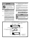
LEFT SIDE
REMOVE AND DISCARD
FOAM BLOCKS
RIGHT SIDE
FAN MOTOR
EVAPORATOR COIL
COMPRESSOR
BACK
TOP VIEW OF UNIT
FRONT
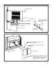
REMOVE AND SAVE
SCREW FOR
RE-INSTALLATION
REMOVE AND DISCARD
SCREWS
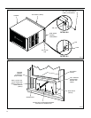
NOTE: DO NOT LEVEL the cabinet from front to back. Make sure there
is approximately 3/8” to 1/2” slope (1/8 to 1/4 bubble on level)
toward the outside of the house.
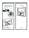
Adjust the support brackets to provide an inside-to-outside slope for excess
condensation drainage (Refer to Standard Window Installation, Figures 20
through 24). Tighten all screws.
Alternate support method A: If you have a wide window sill which prevents
rackets as shown i
n Figure 23, try the following:
Using the elongated holes and different hole locations in the cabinet,
bracket to support the unit’s weight (Figure 23).
Tighten all screws.
Alternate support method B: If the window ledge gap is narrow, try the
as shown in Figure 24. Bend the short piece so it will be vertical when
installed. Adjust the placement as required. Tighten all screws.
STEP 8.
he window side channels and cabinet. (Figure 25).
Make sure you include the depth of the window channel.
STEP 5. Check the window sill and frame to be sure they are in good
STEP 6. CABINET MOUNTING – Raise the lower window 1/4" more
than the height of the cabinet. Carefully slide the cabinet
through the opening until the lower sill plate channel rests
behind the window sill and the top angle rests against the
window (See Figure 19). Center the cabinet within the
opening. Drill three (3) 5/32" diameter pilot holes into window
sill using the holes in the cabinet sill plate as a gui
de. Install
three (3) #12 x 2" long screws (Item 4) (See Figure 19).
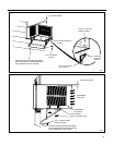
STEP 7. OUTSIDE SUPPORT MOUNTING – Refer to Figures 20 and
21. Assemble the support brackets (Item 1) to the bottom of
the cabinet with four (4) 10-24 1” long screws (Item 2) and four
combination of the elongated holes of the bracket and different
hole locations in the cabinet, to bring the bottom support bracket
pads in contact with the wall. A 1" x 4" or 2" x 4" SPACER
SHOULD BE USED BETWEEN THE WALL AND SUPPORT
THE BRACKETS WHEN INSTALLED ON ALUMINUM OR
VINYL SIDING. Drill 5/32" diameter pilot holes and secure
the brackets to the wall with two (2) 12A x 2" long screws
(Item 4).
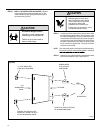
NOTICE
For YOUR security and safety, YOU must
provide a means of preventing the upper
part of the window from opening.
STEP 9. t "J" eht no hsup ,slenap draobgniw eht elbmessa oT ype speed
nuts (Item 9) and spring steel clips (Item 10) (See Figures 26)
on page 31. Secure each panel with two (2) screws (Item 11).
you from mounting the b
set the placement of the
between t


Find Your Products By Category
Please Login
