
0
Owner's of the Whirlpool Ventilation Hood Whirlpool Range Hood gave it a score of 0 out of 5. Here's how the scores stacked up:
7
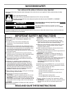
Electrical Requirements
Observe all governing codes and ordinances.
Ensure that the electrical installation is adequate and in
conformance with National Electrical Code, ANSI/NFPA 70 (latest
edition), or CSA Standards C22.1-94, Canadian Electrical Code,
Part 1 and C22.2 No. 0-M91 (latest edition) and all local codes
and ordinances.
If codes permit and a separate ground wire is used, it is
recommended that a qualified electrician determine that the
ground path is adequate.
A copy of the above code standards can be obtained from:
National Fire Protection Association
One Batterymarch Park
Quincy, MA 02269
CSA International
8501 East Pleasant Valley Road
Cleveland, OH 44131-5575
■ A 120 Volt, 60 Hz., AC only, 15-amp, fused electrical circuit is
required.
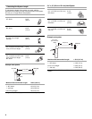
■ If the house has aluminum wiring, follow the procedure
below:
1. Connect a section of solid copper wire to the pigtail
leads.
2. Connect the aluminum wiring to the added section of
copper wire using special connectors and/or tools
designed and UL listed for joining copper to aluminum.
Follow the electrical connector manufacturer's recommended
procedure. Aluminum/copper connection must conform with
local codes and industry accepted wiring practices.
■ Wire sizes and connections must conform with the rating of
the appliance as specified on the model/serial rating plate.
The model/serial plate is located behind the filter on the rear
wall of the range hood.
■ Wire sizes must conform to the requirements of the National
Electrical Code, ANSI/NFPA 70 (latest edition), or CSA
Standards C22. 1-94, Canadian Electrical Code, Part 1 and
C22.2 No. 0-M91 (latest edition) and all local codes and
ordinances.
INSTALLATION INSTRUCTIONS
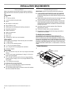
Prepare Location
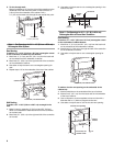
NOTE: It is recommended that the vent system be installed
before hood is installed.
Before making cutouts, make sure there is proper clearance
within the ceiling or wall for exhaust vent.
1. Disconnect power.
2. Determine which venting method to use: roof or wall.
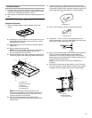
3. Select a flat surface for assembling the range hood. Place
covering over that surface.
4. Lift the range hood and set it upside down onto covered
surface.
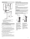
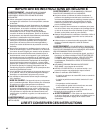
5. If cabinet has recessed bottom, add wood filler strips on each
side. Install screws to attach filler strips in locations shown.
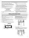
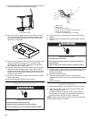
Determine Wiring Hole Location
Cut only one 1¹⁄₄" (3.2 cm) diameter wiring access hole. See
Step 2 for wiring hole location instructions.
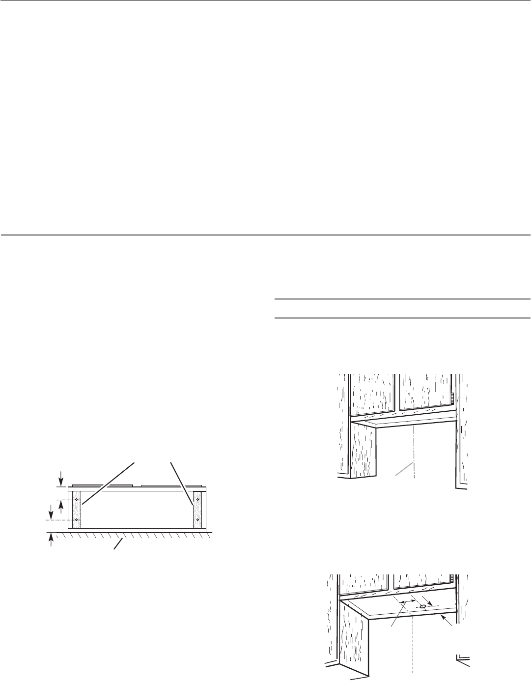
1. Determine and clearly mark a vertical centerline on the wall
and cabinet in the area the vent opening will be made.
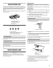
2. To wire through top:
Mark a line distance “A” from the right of the centerline on the
underside of the cabinet. Mark the point on this line that is
1³⁄₄" (4.4 cm) from back wall. Drill a 1¼" (3.2 cm) diameter
hole through the cabinet at this point.
Cabinet
bottom
Wall
3" (7.6 cm)
Wood filler strips
(recessed cabinet
bottoms only)
3" (7.6 cm)
A.Centerline
A.10⁷⁄₈" (27.6 cm)
A
Centerline
1³⁄₄" (4.4 cm)
from wall,
not cabinet
frame
A


Find Your Products By Category
Please Login
