

0
Owner's of the Onkyo Home Theater System Onkyo Home Theater System gave it a score of 0 out of 5. Here's how the scores stacked up:
Kitahama Chuo Bldg, 2-2-22 Kitahama, Chuo-ku, OSAKA 541-0041, JAPAN
http://www.onkyo.com/
18 Park Way, Upper Saddle River, N.J. 07458, U.S.A.
For Dealer, Service, Order and all other Business Inquiries:
Tel: 201-785-2600 Fax: 201-785-2650
http://www.us.onkyo.com/
For Product Support Team Only:
1-800-229-1687
http://www.us.onkyo.com/
Liegnitzerstrasse 6, 82194 Groebenzell, GERMANY
Tel: +49-8142-4401-0 Fax: +49-8142-4208-213
http://www.eu.onkyo.com/
Unit 1033, 10/F, Star House, No 3, Salisbury Road, Tsim Sha Tsui Kowloon, Hong Kong.
Tel: 852-2429-3118 Fax: 852-2428-9039
http://www.hk.onkyo.com/
1301, 555 Tower, No.555 West NanJing Road, Jing’an District, Shanghai, China 200041,
Tel: 86-21-52131366 Fax: 86-21-52130396
http://www.cn.onkyo.com/
The Americas
China
Europe
Asia, Oceania, Middle East, Africa
Please contact an Onkyo distributor referring to Onkyo SUPPORT site.
http://www.intl.onkyo.com/support/
The above-mentioned information is subject to change without prior notice.
Visit the Onkyo web site for the latest update.
(Mainland)
(Hong Kong)
Meridien House, Ground floor, 69 - 71 Clarendon Road, Watford, Hertfordshire, WD17 1DS, United Kingdom
Tel: +44 (0)8712-00-19-96 Fax: +44 (0)8712-00-19-95
SN29401537A
(C) Copyright 2013 Onkyo Corporation Japan. All rights reserved.
* 2 9 4 0 1 5 3 7 A *
D1308-1
E
n
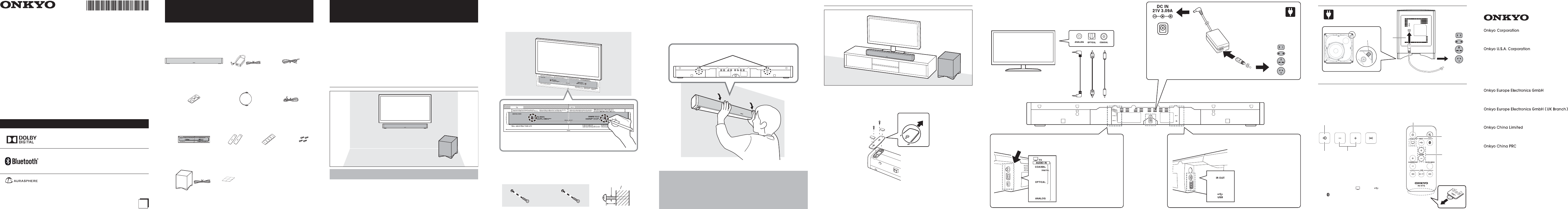
COAXIAL jack
Connect a separately sold cable to
input the sound.
OPTICAL jack
Connect the supplied optical
digital audio cable to input audio.
ANALOG jack
Connect the supplied stereo mini
plug cable to input audio.
IR OUT terminal
Connect the supplied IR flasher to
allow the TV remote control signal
to pass through.
Double-sided tape for
mounting is attached to the
supplied IR flasher side. Mount
to near the remote control
signal sensor of TV with the
double-sided tape.
USB port
Connect a USB flash drive.
3
4
1
1
2
2 3 4 5 6 7 8 9
PREPARATION
Placement
Select an appropriate placement for your environment.
Place the supplied wireless subwoofer in an appropriate place for your use
environment.
To enjoy the best sound, do not place an object on both sides of the unit.
Place the supplied wireless subwoofer within the 33 feet (10 m) distance.
Mounting to Wall
Refer all servicing to qualified service personnel.
Accessories to be prepared: Wall mounting template
PACKAGE CONTENTS
Make sure you have the following items before use.
The number in parenthesis indicates the quantity.
In catalogs and on packaging, the letter at the end of the product name
indicates the color.
Main unit (LB401) (1) AC adapter (1)/
Power cord (1)
IR flasher (1)
Remote controller (RC-877S) (1)
A lithium-ion battery (CR2025) is supplied in
the remote control at the time of purchase.
Optical digital audio
cable 5 ft. (1.5 m) (1)
ф3.5 mm stereo mini
plug cable (1)
Wall mounting template (1)
Stand (2)/Cushion (4)/
Mounting screws (3/8" (10 mm)) (4)
Wireless subwoofer (SKW-B50) (1)/
Power cord (Polarized plug) (1)/
Cushion (4)
LS-B50
Soundbar System
Instruction Manual
1. Attach the template to the position to mount.
Be careful not to make a tape mark on the wall.
Stand at a distance and check its position. Check if it is horizontal.
2. Mark the two screw points with a pen.
Leave 1" (25 mm) between the soundbar and your TV.
3. Remove the template and screw the screws into the wall.
Use the screws with 3/16” (4 mm) diameter.
Keep 5/16” (8.5 mm) of the screw protruding from the wall surface.
Do not use the supplied mounting screws for stand.
Wall
5/16” (8.5 mm)
3/16” (4 mm)
4. Connect all cables to the soundbar.
(o See 7 to 8 pages)
5.
Insert the head of the screw into the keyhole slot of the soundbar and fix it
firmly.
Please confirm that the head of the screw is at the top of the hole.
Do not use the supplied stands.
Keyhole slot
Mounting on Low Board or TV Stand
Accessories to be prepared: Stands, Cushion, Mounting screws
Before placing the soundbar on the boards, attach the supplied stands to prevent
falling.
(Back side)
(Front side)
Connections
Connect the TV and this unit using one of the possible connection cables.
Wireless Subwoofer
1
2
(Bottom)
Cushion
Listening to TV
Turn on the TV.
For details on operation, see the "BASIC OPERATION" (o P.11).
The unit can be operated with your existing TV remote controller. For details
on operation, see the “Using TV Remote Controller” (o P.17).
1
23
1. Turn the power on.
2. Switch the input to TV.
(On the buttons of the unit, switches
in the order of
TV o USB o
Bluetooth.)
3. Adjust the volume.
1
3
2
Please note:
When preparing the screws used for wall mounting, ask qualified service personnel
and give careful consideration to their type, material and length so that they can
withstand the weight. If reinforcement is necessary, use reinforcing plates or anchors.
Onkyo is not responsible for accidents or damage caused by improper installation,
insufficient wall strength, improper screw installation or natural calamity, etc.
Thank you for purchasing an Onkyo product. Please read this manual thoroughly before
making connections and plugging in your new Onkyo product.
Following the instructions in this manual will enable you to obtain optimum performance and
listening enjoyment from your new product.
Please retain this manual for future reference.
Trademarks and Licensing
Manufactured under license from Dolby Laboratories.
Dolby and the double-D symbol are trademarks of Dolby
Laboratories.
The Bluetooth® word mark and logos are registered
trademarks owned by Bluetooth SIG, Inc. and any use of such
marks by Onkyo is under license. Other trademarks and trade
names are those of their respective owners.
AuraSphere™ is a trademark of Onkyo Corporation.
AuraSphere is a listening experience technology developed by Onkyo
Corporation and Sonic Emotion ag.


Find Your Products By Category
Please Login
